PHY2028 SimSheet-03
SPICE Models and Subcircuits
Homework and Background
- Design a high-pass Butterworth filter with a corner
frequency of 5kHz using a 741-type op-amp and only standard E12 resistor values.
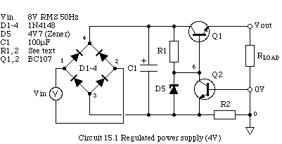
- Circuit 15.1 (see below) is a simple power supply. The AC input is
full-wave rectified by diodes D1-4 and smoothed by C1. The zener diode,
D5 holds the base of transistor Q1 at a constant voltage. The transistor
act as an emitter-follower so the voltage at the emitter remains
constant. R2 senses the current delivered to the load and, and when the
base-emitter voltage of Q2 exceeds about 0.5V Q2 conducts and reduces
the the supply output current. Calculate:
- an appropriate E12 value for R1 if the Zener diode is to operate with a 3mA bias current;
- an appropriate E12 value for R2 so that the output current is limited to about 50mA;
- the voltage ripple at the collector of Q1.
Note: The work next week will involve field-effect transistors. Please prepare by reading Storey chapter 6. For the purposes of PHY2028, you do not need to know about the details of
how they work, just what they do and some examples of how they are used.
Practical Session
You may find it helpful to review the following sections of the SPICE 3 User's Manual before starting the practical work:
CW121004-04.CIR uses the SPICE DC-sweep analysis to plot the
output characteristic of the BC107BP transistor model
(see Storey (1998) §7.6.3 / Storey (2006) §8.5.3). Study the source file to discover what is
being plotted, draw the circuit diagram in your notebook. Explain how
the graph of collector current IC vs base
current IB deviates from ideality.
Devise a source file that plots the V-I characteristic of the BZX84C4V7 zener diode model over a range of currents -100mA < I < +100mA. Use Spice to calculate (to 3 significant figures) the voltage drop across the
diode when it is reversed-biased with (a) 10mA, and (b) 1mA.
Milestone 1
Devise a Spice source file to simulate circuit 15.1 using the values you
calculated above. [Note: node 3 is left free to float and
Vout is the voltage across the load.]
Use RLOAD=330ohm and run a transient analysis from 0 to 40ms.
What is the DC voltage and ripple at the the load? Include a plot, or
sketch of the ripple at node 4 and the output in your notebook. You will
need to specify the plot ylimit
parameters to see the ripple properly.
Milestone 2
Perform a series of transient analyses running from 20ms to 40ms, and use the results to plot graphs showing the average (a) voltage across, and (b) current passing through R
LOAD as a function of load conductance (
i.e. 1/R
LOAD). Explain how your graphs demonstrate the correct operation of the circuit.
Milestone 3
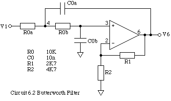
CW121004-05.CIR is a Spice source file for circuit 6.2 which you investigated in the laboratory (Worksheet 6). A Butterworth filter has a fairly linear phase vs frequency relationship so that that each harmonic of the input signal effectively experiences a constant time-delay Td.
Run the simulation and type the following interactive commands:
- setplot ac
- plot phase(v(6)) (-frequency*0.056) xlimit 0 3kHz ylimit -200 0 linear
- plot tran.v(1) tran.v(6)
Explain in your notebook what each of these commands do. At what frequency does the phase-frequency relationship differ by 5% from linear? Calculate the time delay Td and compare it with the results of the transient analysis.
What causes the minimum in the frequency response at about 60kHz (use plot db(v(6)) to see it for yourself)?
Milestone 4
Compare the results of this simulation with the results you measured in the laboratory (if necessary, change the values of the components to the ones you actually used).
Use SPICE to calculate the frequency response of the high-pass filter you designed as homework.
Use both LF411/NS and LM741/NS op-amp models and comment on any differences. You can show the
results of two separate analyses on the same graph using a sequence of commands such as:
- setplot ac3
- plot db(ac1.v(6)) db(ac3.v(6))