|
Overview
Facilities
Ultrafast laser
Ultra high
vacuum
sputtering
X-Rays
AGM
Magnetometry
MOKE
Magnetometry
Magnetotransport
People
Vacancies
|
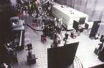
 In this experiment we observe extremely fast magnetic processes by
means of an optical pump-probe technique. An ultrafast Titanium-sapphire laser supplies pulses of light, less than 10-13s in
duration and with wavelength tuneable in the range 700-1000 nm, at a
repetition rate of 82 MHz. Each pulse is divided into two parts and
the first part is used to "pump" the sample. The second is time delayed before being used to "probe" the sample at a later time. Every
pair of pulses pump and probe the same process. By averaging for
just 1s we collect 82 million events which leads to an excellent
signal to noise ratio! The time delay can be varied by reflecting the
probe beam off a mirror mounted on a translation stage, so that the
sample response can be mapped out as a function of delay time.
In this experiment we observe extremely fast magnetic processes by
means of an optical pump-probe technique. An ultrafast Titanium-sapphire laser supplies pulses of light, less than 10-13s in
duration and with wavelength tuneable in the range 700-1000 nm, at a
repetition rate of 82 MHz. Each pulse is divided into two parts and
the first part is used to "pump" the sample. The second is time delayed before being used to "probe" the sample at a later time. Every
pair of pulses pump and probe the same process. By averaging for
just 1s we collect 82 million events which leads to an excellent
signal to noise ratio! The time delay can be varied by reflecting the
probe beam off a mirror mounted on a translation stage, so that the
sample response can be mapped out as a function of delay time.
 We use the Magneto Optical Kerr Effect to sense the instantaneous
magnetic state of the sample. The sample magnetisation causes the
plane of polarisation of the probe beam to be slightly rotated.
Although this rotation is small we can measure the rotation to about
1 microdegree with an optical "bridge" detector that consists of a
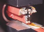
polariser and two photodiodes. We have two methods of pumping the
sample. Firstly we may directly excite electrons in the surface of
the sample with the optical pump pulse. Secondly we can use the
optical pump pulse to trigger a magnetic field pulse by using a
photoconductive switch structure. This consists of a transmission
line structure deposited on a semi-insulating direct band-gap
semiconductor substrate. A bias voltage is applied between the tracks
of the transmission line. The substrate only conducts when the
optical pump pulse creates free carriers in the gap between the
tracks. At this point a current pulse is generated in the
transmission line. The magnetic field associated with the current is
used to "pump" the sample that is overlaid on the transmission line.
The current profile can be checked either by attaching an oscilloscope
to the transmission line, or by using the probe pulse to divert
current into a third Au track and so generate a current
autocorrelation curve.
We use the Magneto Optical Kerr Effect to sense the instantaneous
magnetic state of the sample. The sample magnetisation causes the
plane of polarisation of the probe beam to be slightly rotated.
Although this rotation is small we can measure the rotation to about
1 microdegree with an optical "bridge" detector that consists of a
polariser and two photodiodes. We have two methods of pumping the
sample. Firstly we may directly excite electrons in the surface of
the sample with the optical pump pulse. Secondly we can use the
optical pump pulse to trigger a magnetic field pulse by using a
photoconductive switch structure. This consists of a transmission
line structure deposited on a semi-insulating direct band-gap
semiconductor substrate. A bias voltage is applied between the tracks
of the transmission line. The substrate only conducts when the
optical pump pulse creates free carriers in the gap between the
tracks. At this point a current pulse is generated in the
transmission line. The magnetic field associated with the current is
used to "pump" the sample that is overlaid on the transmission line.
The current profile can be checked either by attaching an oscilloscope
to the transmission line, or by using the probe pulse to divert
current into a third Au track and so generate a current
autocorrelation curve.
|