PHY2028 SimSheet-02
AC Circuit Analysis with SPICE
Background Work
Read the following sections in the SPICE 3 User's Guide:
- Types of analysis:
- Independent Sources
- Diodes
- Interactive-mode commands to display and manipulate results:
Practical Session
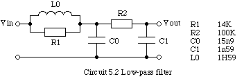
Exercise 5.2 of Worksheet 5 was to analyse
circuit 5.2 by hand. That exercise, you will recall, required some
rather tedious algebra and it is much easier to use SPICE. If MacSpice is
already running quit
and restart it to make sure that the plotnames specified below correspond to the
ones you will create. Download the pre-prepared source file (CW121004-08.CIR) for circuit 5.2 and
open it with MacSpice. The file contains contains several interactive
commands which are executed immediately it is opened - inspect its
contents (use MacSpice 'edit' command which will open TextWrangler). Next try
the following commands:
- echo $plots
- setplot ac1
- plot db(out)
- plot phase(out)
- setplot tran
- plot in out
In your notebook: write a brief explanation of what each of these commands does,
record the frequency and value of the maximum in the frequency response,
and sketch the transient response to a step input.
Note: Dragging the MacSpice cursor between two points on a plot will display the difference in their values.
Milestone 1
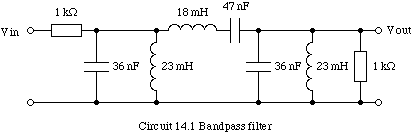
Write a Spice source file for circuit 14.1 (Reminder: always include a
copy of the circuit diagram and the source file in your notebook).
Milestone 2
Investigate the performance of circuit 14.1. In particular:
- Plot the frequency response and find the upper and lower -3dB frequencies. How flat is the pass-band?
- Plot the phase response.
- Calculate the transient response of the filter to a single pulse of amplitude 1V and width 300µs.
- Identify the type of filter and give your reasons.
Milestone 3
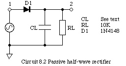
CW121004-07.CIR is a Spice version of
Circuit 8.2, the passive half-wave rectifier circuit you investigated in
the laboratory. Use it to repeat your investigation of this circuit
(i.e. Mile 3 of Worksheet 8)
using Spice. The transient analysis in the source file uses TSTART=1ms,
why?
[Hint: Check that the transient analysis runs over a precise number of
cycles. Instead of the DMM use the linearize command to
create a new set of vectors interpolated onto equally spaced timepoints,
and then use the mean()
function. You can use the pointplot keyword with the
Plot command to see the effect of the linearisation.]
Milestone 4
Download the PHY2028 SPICE library (PHY2028.LIB) and place
it in the Home:Documents:MacSpice: folder. This library contains models and
subscircuits (see also PHY2028 Data-sheets)
defining the active components to be used in the following exercises.
Write a Spice source file to investigate the full-wave rectifier,
circuit 14.2. Assume that the diodes are type 1N4148, the AC supply is
50Hz 10Vrms, and select a value of load resistor (R1) so
that it passes an average current of approximately 25mA. Sketch the
waveform at the output node when C1=10µF. Find what value of C1
would be required if the ripple at the output must be less than 250mV.
[Hint: Use "tran 50us 250ms 200ms 50us" to perform the analysis.]
Milestone 5